Hybrid Modelling
We’ll begin by explaining an approach referred to as hybrid modelling. This approach uses both solid and surface modelling techniques in order to achieve the end result. If you’re new to surfacing, this method is an easy introduction as it requires as few as one surface to get going. There are a few different tools and features that you can easily utilise to begin hybrid modelling.
Up to surface
Up to surface is an end condition within a feature. To use up to surface, the surface must exist before the solid extrude feature is created. When in the extrude feature, choose up to surface from the end conditions drop down and pick the surface.
Cut with surface
This feature uses a surface as a cutting tool. The surface must fully intersect the body that is to be cut, and you can control which side of the surface that the volume should be removed from.
Replace Face
Replace face has a similar workflow to cut with surface but with replace face, the surface does not have to intersect the solid, although it can. Replace face is also useful for where the surface intersects the solid across multiple regions, but you only want it to affect a single face.
All of the methods above achieve the same results but offer different workflows. You’ll find the more you work with surfaces that it is always good to have a few different tools in your toolkit!
Fit Spline
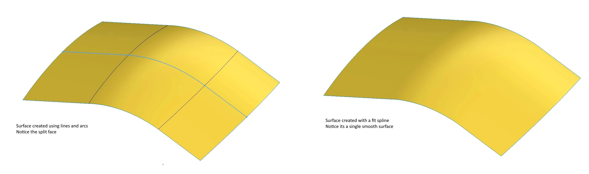
When surfaces are created you will notice that you get multiple faces if different entities exist in the underlying sketch. Whilst this isn’t necessarily a bad thing, sometimes this is undesirable, and can cause issues with selection later on. Using the fit spline command will reduce the number of entities within a sketch by doing a best fit across any endpoints and this will result in a single smooth surface.
Selection Manager
Sometimes fit splines are not appropriate or possible, resulting in you having to select each element that makes up the surface when using it within a feature. This can be time consuming and can also lead to undesirable results because Solidworks treats each selection independently,
Instead you will want to use the selection manager to tell SolidWorks to treat the selection as a single entity. Loft, sweeps, and boundary surfaces all support it. Simply right click and choose the selection manager and a new popup will appear. There are various options to it, allowing you to select loops, or simply click the appropriate edges individually. Not only will SolidWorks now treat the selection as a single entity, the selection manager is really useful as the edges can actually be from different surfaces.
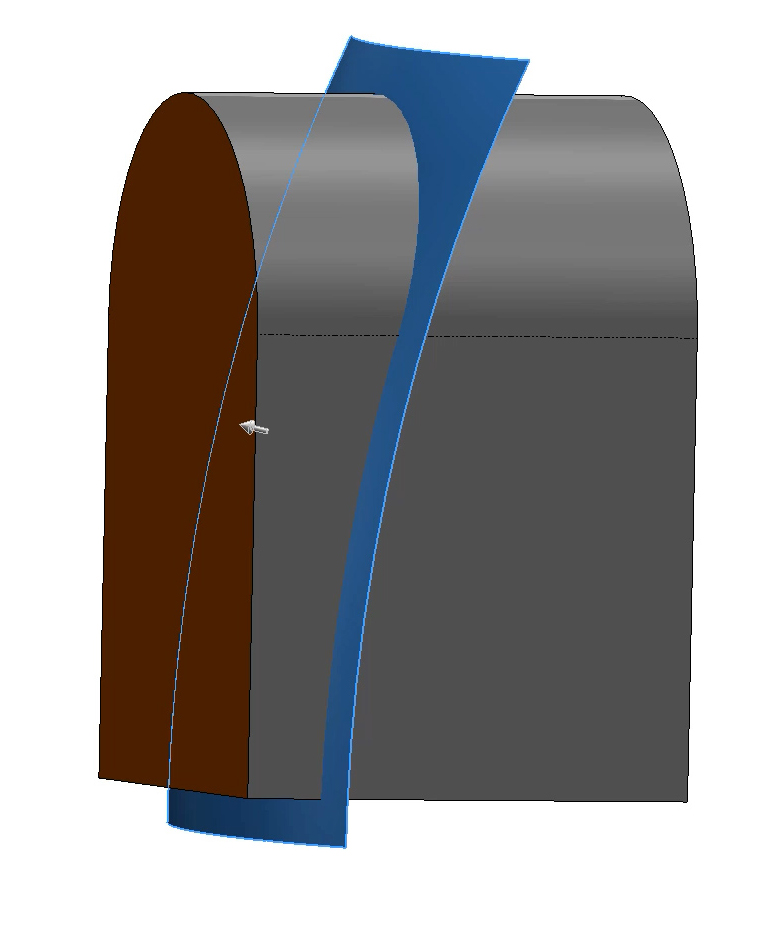
Use Construction Surfaces
Construction surfaces are those that are used to help build a model but don’t actually form part of the final model. They are extremely useful, especially when wanting to control surface tangency, curvature, and important manufacturing details such as draft angle.
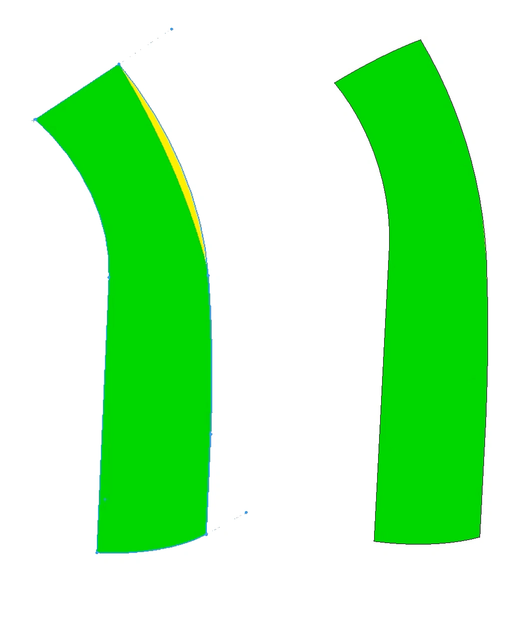
The two images show the same boundary surface. Draft analysis is enabled so we can see the areas on the surface where draft is below the desired 5 degrees. Green is achieving the desired draft, yellow is not.
The first image has been created using a boundary surface and four sketches. With sketches we are unable to control tangency and therefore we can see the yellow area appear where the draft angle is below 5 degrees.
The second image uses three of the four sketches but then a construction surface for what would have been the fourth edge. This construction surface is that fourth sketch extruded as a surface in the opposite direction with draft applied.
When using construction surfaces, you are able to add tangency to them, which in this case has helped to control that draft and maintain 5 degrees throughout our surface.
Delete bodies
In general, surfacing will result in more features than solid modelling and often more bodies. This is because surface bodies will be created that won’t end up as part of the final model. These can easily be hidden away using hide/show but to keep the Feature Manager tidy, they can also be deleted. Add a delete bodies command and select either the bodies to delete or the bodies to keep. This can be done incrementally throughout the model to keep the tree looking tidy, or alternatively you can just delete all the unused bodies at the end.
Trim
When using a pure surfacing approach, it’s usually required to trim surfaces back to one another and this is done using the trim command. There are two main options when within the trim command, standard and mutual.
Standard only requires one selection for the trim tool but can include multiple bodies to trim. The trimming tool can be a surface, plane, or sketch and will trim through the intersection of the plane or surface, or the projection of a sketch.
When using mutual, multiple surfaces can be selected for the trim tool or trimming surface. This will create a larger selection of trimmed pieces and it is often a lot more complicated to achieve the end result. However it is very powerful and when used correctly can get you to the end result with fewer features.
If you are just learning surfacing, creating a larger amount of trim features that utilize fewer surfaces can often be the easier way to understand what is going on.
Knit Regularly
Knitting is the feature used to join multiple surface bodies together at a common edge. Often you will be building a number of surfaces using different techniques and then the knit command is used to join them into one surface body and often also force that surface to become a solid. For large complex models, it is good practice to knit surfaces as you go. The last thing you will want is to get to the end of a large surface model, go to knit it together, only to realize that it can’t be done. So instead, knit surfaces to each other incrementally, therefore if there are any gaps between the edges or errors, these can be addressed earlier on.
As an extra tip, make sure to keep an eye on the edge colours.
The edges of a solid will be black, as will the knitted edges of a surface. While the open edges of a surface will be blue.