If you’re new to sheet metal, make sure to check out our SolidWorks Sheet Metal introduction video and blog which covers the basic concepts and features to get started.
Pick the best profile
When modelling in SolidWorks, It’s important to choose the best profile to start with, and the same applies when using the sheet metal tools.
When using the base flange method, there are two approaches that can be used to model the part; an open sketch profile; or a closed sketch profile.

When an open sketch profile is used, the sheet metal thickness is offset about the sketch and the length of the part extruded. As the bends are being extruded in this initial feature, no details such as chamfers or holes can be added at this stage, and instead they are added as separate secondary features.
When using a closed sketch profile, because the thickness of the sheet will be added perpendicular to the sketch, detail such as holes can be added in this initial feature, however no bends can be captured using this method. Bends would then need to be added in as secondary features.
This is a really simple explanation, but choosing the best profile can save a lot of time and also make the model easier to modify at a later stage as it determines where key dimensions appear in the model.
Edit Flange Profile
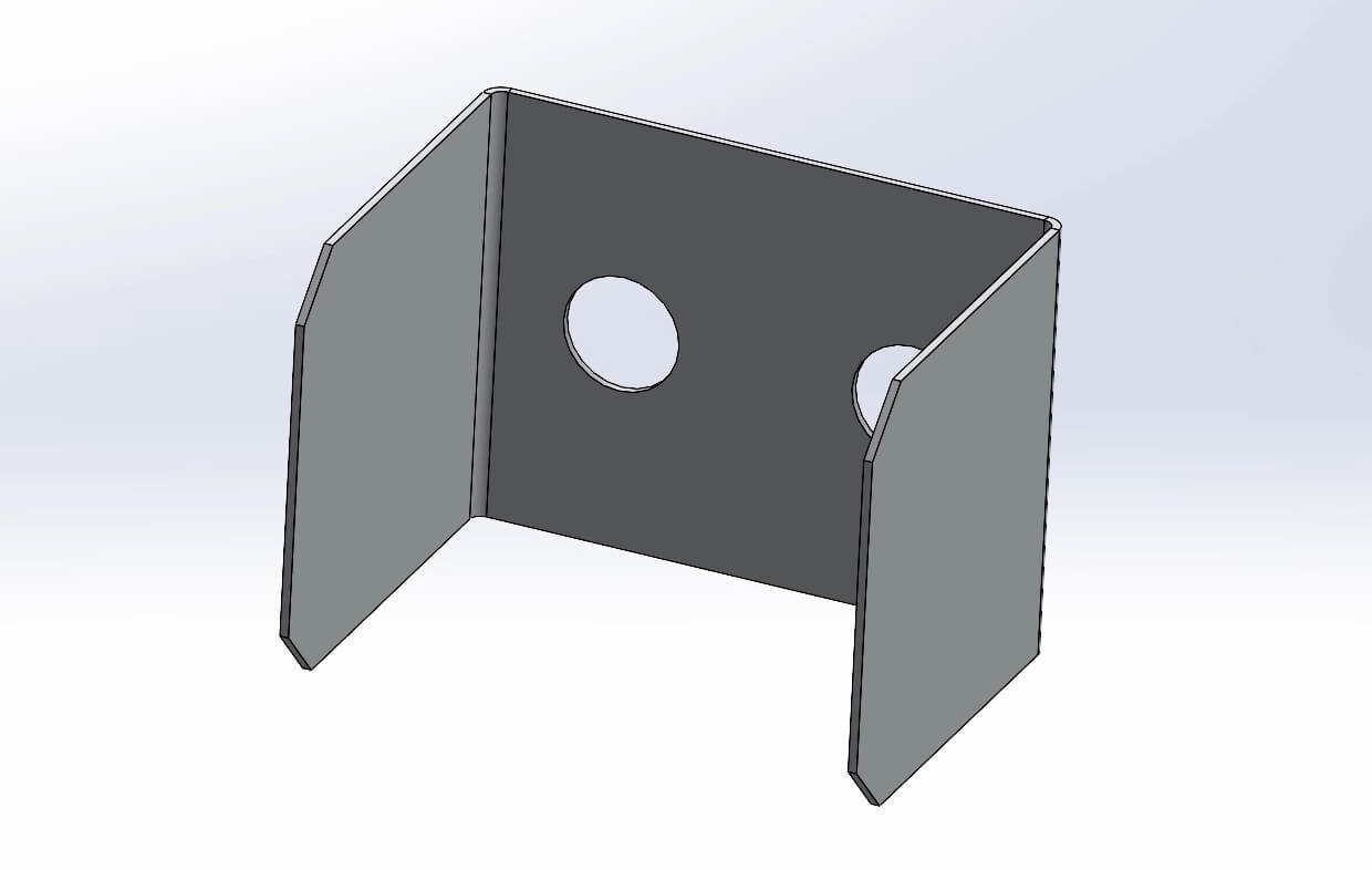
The edge flange tool allows a bend to be added to the edge of a sheet metal body. The default is that this flange will be rectangular in shape and run the entire length of the selected edge. But sometimes there is a need to modify the geometry of the flange to create a different profile. This can be achieved using ‘Edit Flange Profile’.
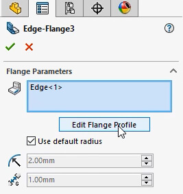
Clicking ‘Edit flange profile’, enters sketch mode for the flange. From here, any part of the sketch can be adjusted, such as the position or offset from the end of the selected edge, additional material being added, or holes being captured at the same time.
Because the sketch has been modified, some of the values in the edge flange properties are no longer linked so it’s important to define the sketch as you would for any other sketch by adding relations and dimensions where needed.
Normal Cut
Sheet metal parts are usually profiled using a laser or plasma cutter before being bent into shape. These methods cut the material perpendicular to the flat sheet, resulting in a cut face that is 90 degrees.
Because this is how sheet metal is manufactured, it is important to ensure that SOLIDWORKS models are created in the same way to avoid issues further down the line.
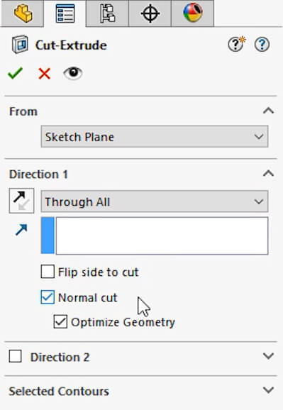
When removing material from a sheet metal part using a cut feature, ‘normal cut’ can be enabled within the properties. Normal cut ensures that any cut faces will be perpendicular to the flat sheet when unfolded and therefore can be profiled using a laser cutter.
Normal cut may need to be disabled for holes that are being added outside of the laser cutting process, such as a drill hole that is going to be added after the part has been bent. This type of hole does not have to be perpendicular to the flat sheet.
Unfold/Fold
Adding cuts across a bend can be achieved whilst the part is in a folded state but it can sometimes be difficult to get the required cut shape. Adding the cut whilst the part is unfolded instead allows more control.
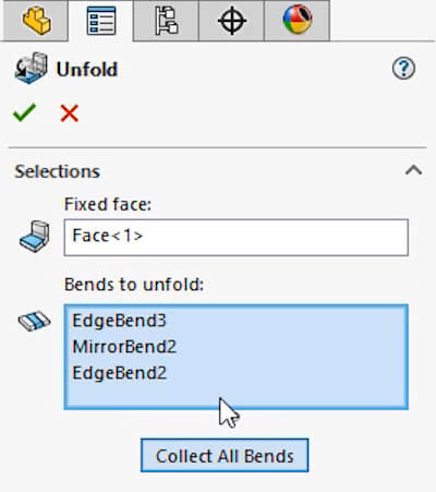
To unfold a sheet metal part, click unfold on the sheet metal tab. A fixed face needs to be selected and either a single bend, multiple bends, or all bends can be selected to be unfolded.
Once the bends are unfolded, the cut features can be added in and then the fold feature is used to fold the part back up.
It is important to use fold/unfold as these both get added to the history in the feature manager. Although the flat pattern button looks as though it is achieving the same thing as using unfold, flat pattern doesn’t add a feature to the tree and therefore can’t have cut features added after it that can then be folded back up.
Link to Thickness
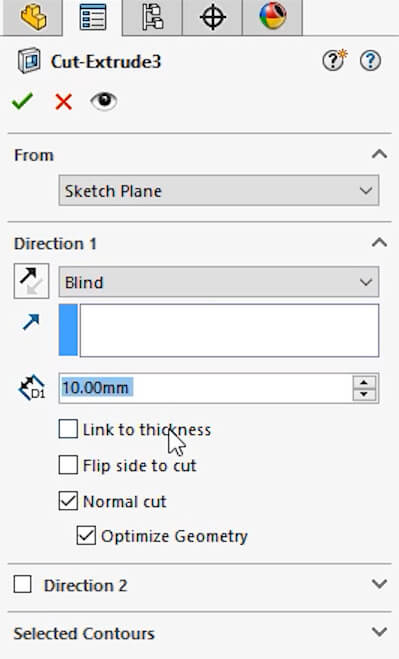
It’s common to need to add cuts that only pass through the sheet thickness once, such as through the face of a flange, so rather than having to manually specify a blind value, or pick up to surface each time, when adding a cut to a sheet metal part, an option called ‘link to thickness’ can be ticked. If the sheet thickness is changed, the depth of the cut will change too.
Right click to export to DXF/DWG
For instances when a 2D drawing is not needed but the sheet metal part still needs to be sent to the laser cutter, export to DXF can be used directly from within the 3D model.
Right click on a sheet metal body or part and choose export to DXF/DWG.
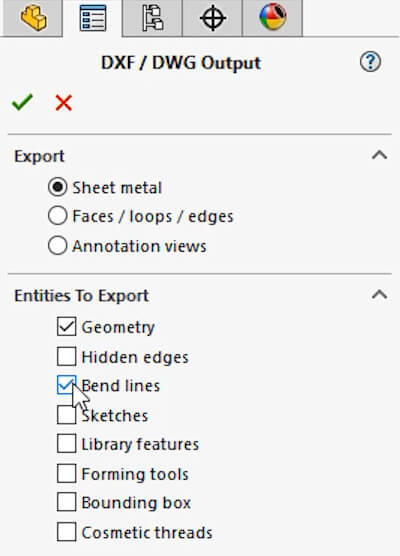
In the properties pane select sheet metal under export and then more options become available to control what information will be saved into the dxf, such as hidden lines, bend lines and sketches.
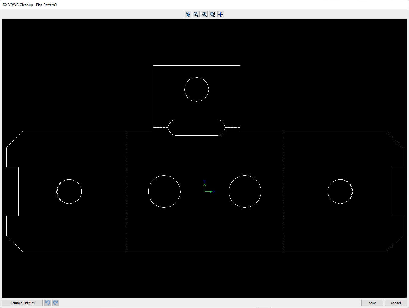
The output is a 1 to 1, flattened, 2D file which can be used for manufacturing.