The team here have all worked at either CAD software developers, such as Autodesk and SolidWorks, or at CAD resellers, and after recent discussions with some of our users, we thought it would be valuable to share some of our top tips that we’ve picked up along the way, starting with a few quick fire tips for furniture design in SolidWorks.
Multibody
There are a number of different modelling techniques in SolidWorks, but often, with furniture design, the multibody approach is the most powerful and efficient as it allows you to control nearly all aspects of your design from a single part file.
Multibody design allows multiple bodies to exist in a single part file. Multibody solids can be manipulated in the same manner as single solid bodies. This includes adding and modifying features, as well as changing the names and colours of each solid body. The benefit of this is that parts are designed around one another, with overall dimensions shared and easily used to drive the entire design. This can avoid problems with items not fitting together as expected in assemblies and avoids toggling between multiple part files when a change is needed.
Weldments
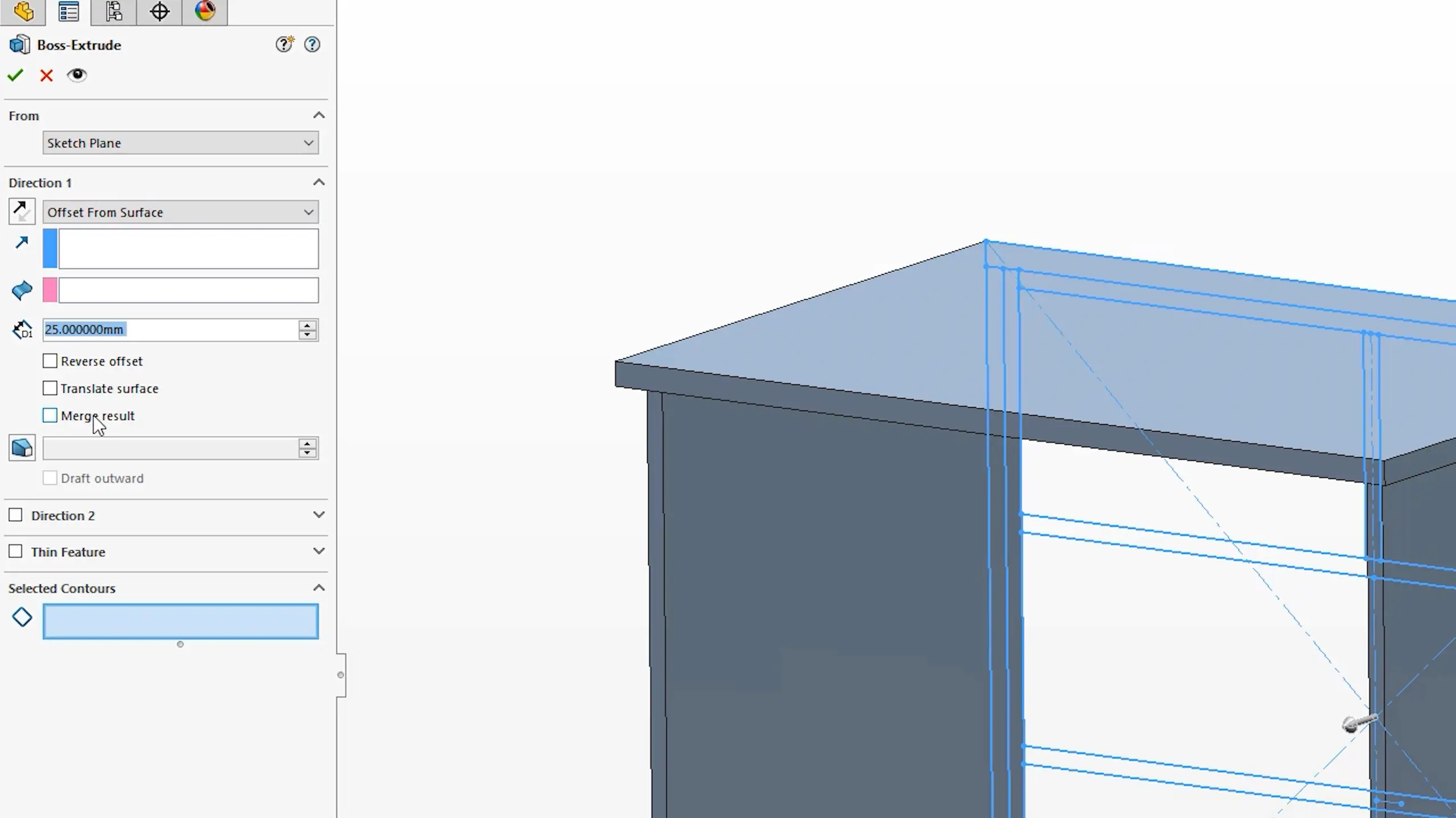
By default, SolidWorks will try to merge all features together, one way to stop this is by unticking the ‘merge result’ box when adding a new additive feature. It's easily forgotten though, so ideally you won’t want to do this for every feature you create, so a good tip is to tell SolidWorks to treat your part as a weldment. Do this by clicking the "weldment" icon on weldment tab manager.
Treating your part as a weldment has several advantages for furniture design, one being that it changes the default behaviour for the file to not merge additive features, removing the need to constantly untick the option.
You can also quickly populate material for items that are cut from length using the weldment structural member tool. This allows you to send custom profiles down a sketch line to create frameworks and moldings. You may also want to look into 3D sketches as often combining structural members with them can be very efficient.
Equations and Global Variables
With furniture created from panels, standard thicknesses are often used across the design, but these may change depending on material availability, quality and price point. Being able to change these sheet thicknesses quickly can be achieved by using global variables. Global variables allow multiple dimensions to be linked together. If one dimension changes, they all do, which means you won't need to go in and edit lots of individual dimensions saving you lots of times.
Create a global variable from either within the dimension dialogue by entering a name and value, or by browsing to the equations dialogue.
Global variables are great because they can be used between models, and configured. It is also worth pointing out that they can be utilised within equations, so you could put some intelligence between dimensions, for example you could ensure that the shelves are always 0.75 of the wall thickness.
Cut-Lists and Bounding Boxes
Another benefit of using multibodies is the cut-list table which is automatically created providing the weldment feature has been enabled. Cut-lists are great for anything that comes in length or sheet material.
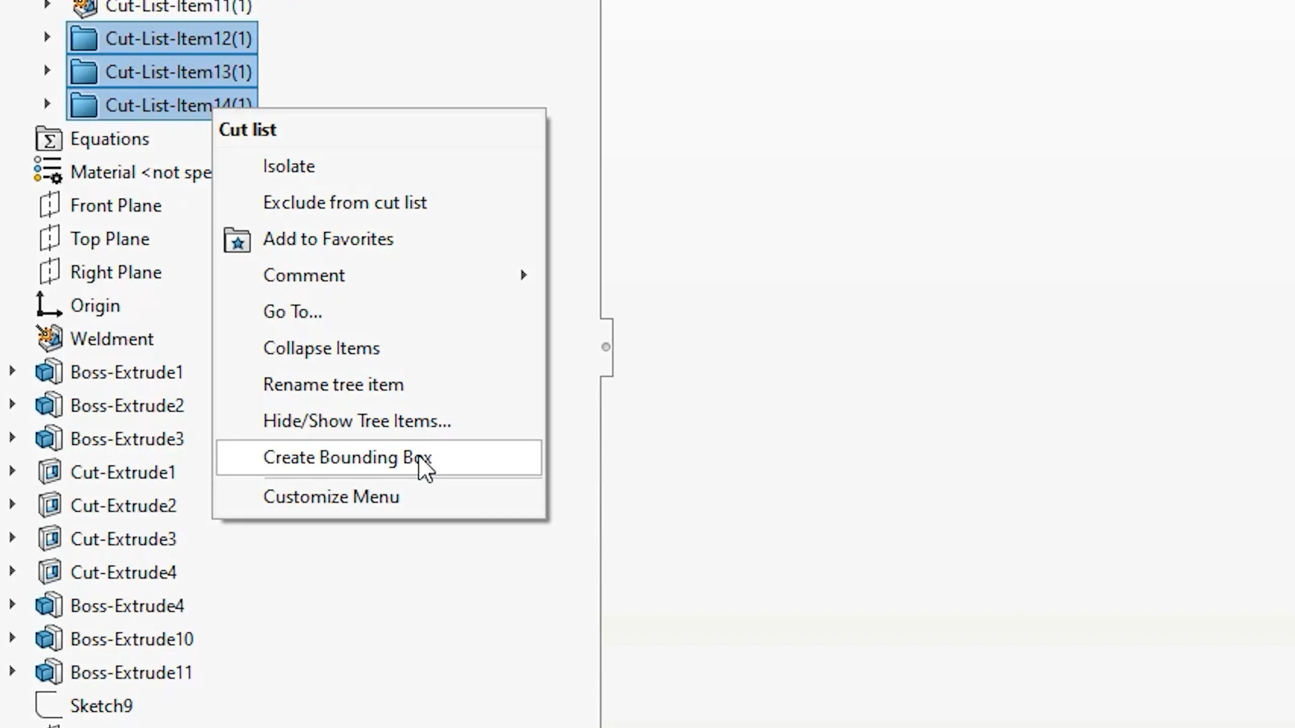
To see all of the available cut-list information, make sure to create a bounding box for anything that comes in panel or board. This will then bring through width, height and thickness values. You can also get the cut length automatically for bodies created using the structural member tool. Cut from length material created using the structural member tool will automatically pull through the required lengths for each body.
Library Features and Smart Components
With furniture designs you may find yourself repeating the same features or adding the same stock items to every design. Library features and Smart Components can really help to speed up adding these common attributes. For example, a library feature allows for predefined features to be created once and then saved into your library for future use. You can then easily add the library feature to you model with a simple drag and drop, removing the need to manually create features. Library features can even have variables specified that can be modified on placement.
Smart Components are similar to library features, but they bring parts into an assembly environment, such as a hinge, bracket, or handle and can also place secondary parts as well as other features such as location holes. By making a component smart, you link other components and features to the Smart Component. When you add the Smart Component to an assembly, you have the option to include or exclude the associated components and features.
Configurations
Furniture often comes in a variety of heights, widths and depths with the underlying design being exactly the same. This is where configurations can help. Configurations are extremely powerful and allow multiple design pathways to exist within a single file. Each configuration can have unique features, dimensions, or materials, allowing you to create different versions of a design without having to create a completely new file. Its worth noting that you can create configurations in both the part and assembly environment.
Whilst the configuration manager maybe the initial way to create your first configuration, using a confirmation table is a much nicer way of visualising and controlling the parameters. If you want to get really complex then you can also use Microsoft Excel based design tables. Once you really get into configurations you may also want to look into the configuration publisher which which helps filters though configurations using defining properties, and means you pick parameters to choose a configuration when insetting into an assembly rather than choosing the configuration name.
2D Drawings
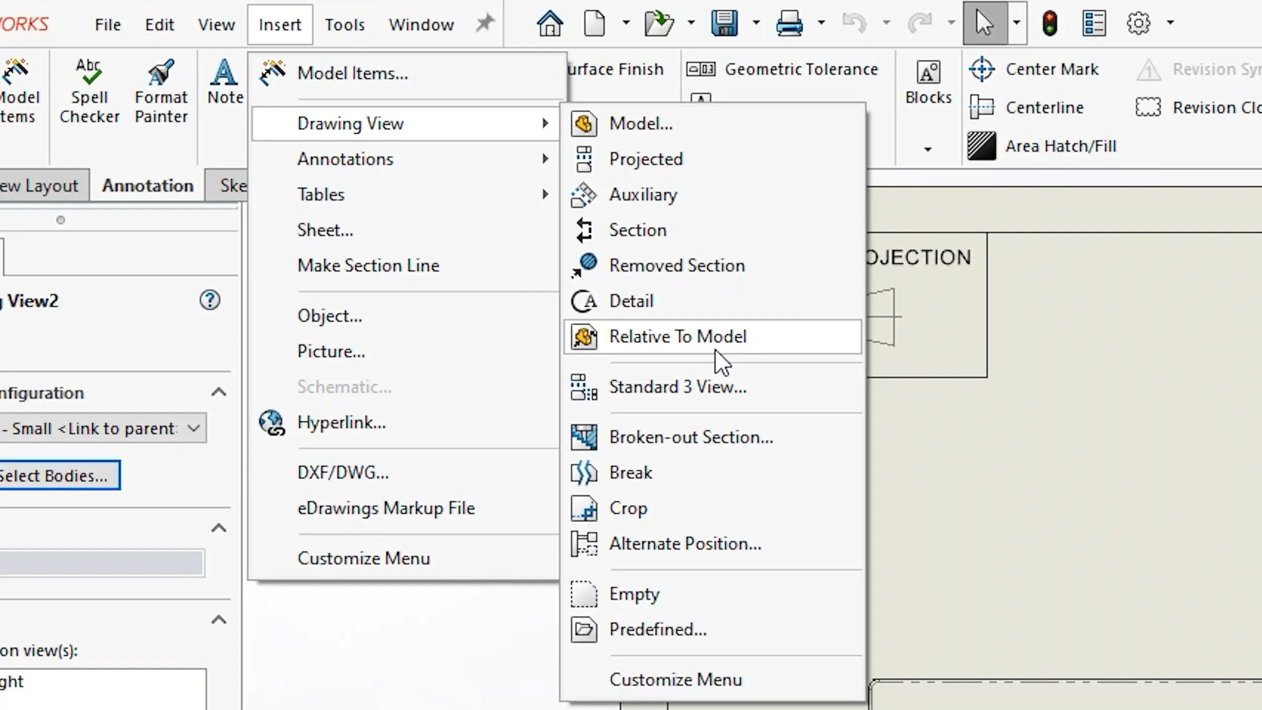
Laying out a 2D drawing from a multibody part file is just the same as any other SolidWorks part or assembly file. However there are some extra options, that are not immediately obvious that can be used if you want to show individual bodies from the multibody part file. The first is simply using the selected bodies button to isolate specific bodies within a view.
If you also need to change the orientation of a body, the relative to model option can also be used to reorientate a specific body or bodies.
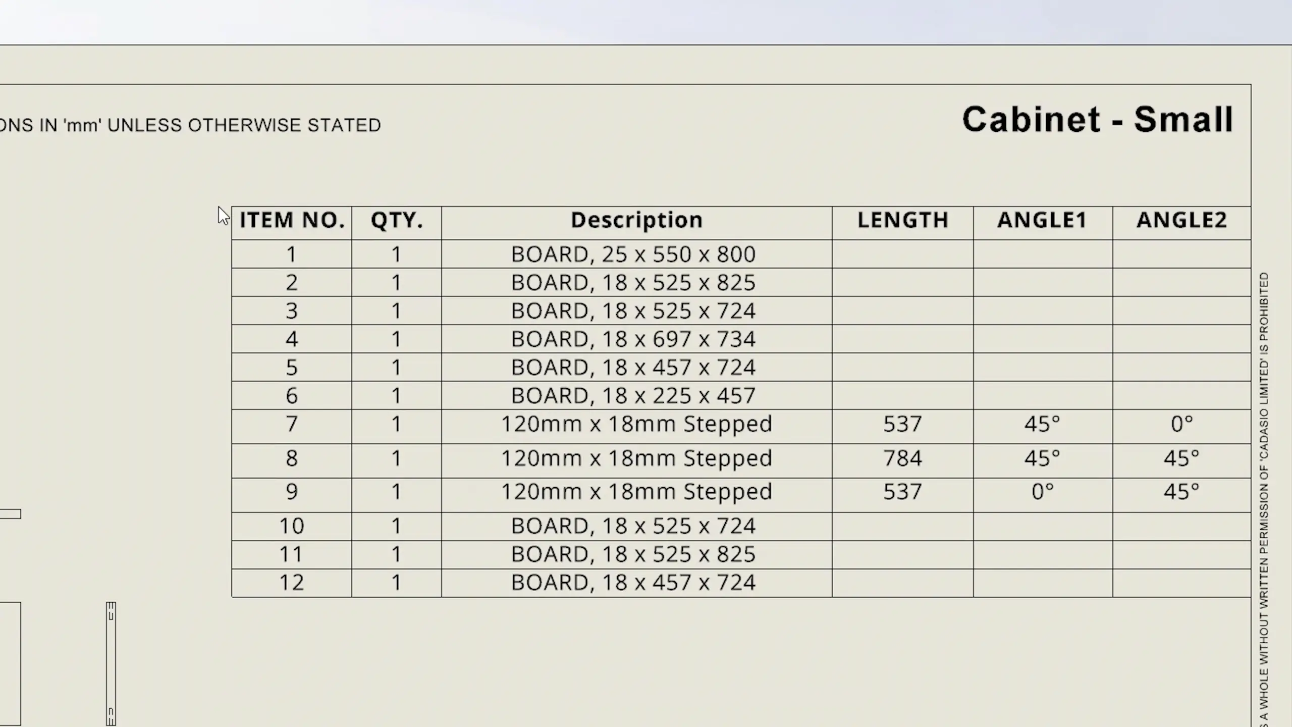
Cut-list information can also be shown in the 2D drawing, simply choose cut-list from the tables drop down, select a view, and click to add it in. Extra columns can be added to show the additional cut-list information such as thickness and board dimensions.
Don’t forget that for your instruction manuals, Cadasio is a great solution that allows you to create 2D, and 3D interactive assembly instructions straight from your SolidWorks CAD data. Get our SolidWorks addin now and get started for free.